CST rfid antenna with complex port
hy I am working on a microstrip rfid antenna and i Have problem on port modelisation
It shoud have an input ampedance about 25.5+145j so i used a discret port of 25.5 ohm for the real part and a capacitor lumped elemnt in serie of 0.1199 picofarad
to model the imaginary part but this did not work the imaginary part still around zero on the disired frequency wihle the thioric is about 145
does some one have an idea about this or some exmple of cst antenna with complex port and thnks
Why do you need the capacitor?
You can check the impedance in the results, for example in the smith chart.
Hy thanks for your reply
in fact CST can't modeling a complex port it only had a real modelisation like 50 ohm impedance
so to design an rfid structure with complex port we need to add a lumped element to modeling the imaginary part
or the reactance part as the theory and the cst tutorials said can be seen as the following :
Img = 1/2*pi*F*C where f is the frequency and C is the capacity
so for img = 145 ohm and f =915 we find C = 1.199 e-12 F
a put the capacity in serie in the design but i get no thing I just cant figure where the problem is I'am convencid there is some thing to change with in the cst but ican't know exactly
When you simulate the antenna with a 50 Ohm port without the capacitance you'll get the impedance of the antenna for example if you look on the smith chart.
But the S11(to the RFID Chip) and the accepted power of the antenna are wrong since CST uses the 50 Ohm port. You have to calculate the values by yourself.
When you insert the capacitance, the imaginary part of the simulated input impedance should be zero. The imaginary part of the antenna impedance and the impedance of the capacitor are summed up to zero, which gives you a zero imaginary part seen from the lumped port.
And if you use a port with 25.5 Ohm the S11 should be correct.

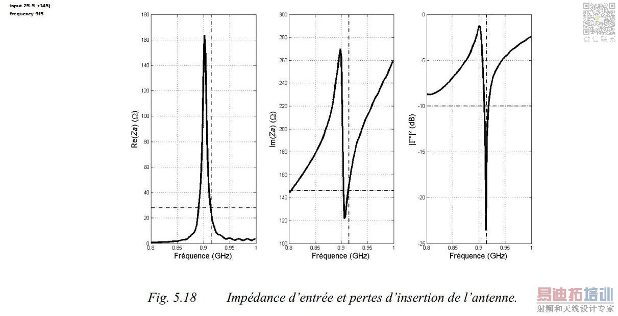
and this is the result from the paper
i have simulate the structure using hfss and it has gave me a lojic curves like expected
i thought now that CST also make true calculation but the desplay still yet have problem i wonder if there is any setting needed to make him take acount of the capacitor as part of port
here i attch the expcted results simulated with cst on the paper published
In CST you'll get the impedance seen by the port. So if you add the capacitor the capacitor is treated as a part of your antenna.
When you remove the capacitor you should get the 145j Ohm.
As far as I know you can't make a port with a complex impedance.
thank's i have found the apropriate value of the real part and the imaginary part of the impedance but still the S11 the return loos i Can't make it like desired :(
Have you calculated the S11 by your own with the impedances of the antenna and the chip?
Unfortunately I think this is the best way to do it, then you know that your calculations are correct.
But if you set the port to the real value and include the capacitor you should get the S11. You can compare this to your calculation with the impedances (which is done without the capacitor)


