Simulation of a CubeSat in CST
Please can anyone tell me how I can simulate a CubeSat with the frame and antenna in CST and if there are any resources or examples available ?
Please help me thanks in advance :)
you can simulate antenna but you cannot simulate cubesat in CST. If you have your CubeSat design (circuit), you can make/draw the circuit in CST. however, simulating entire CubeSat is often not nessasasry. RF circuits are often simulated in parts.
Thanks for the reply...do the antenna parameters change when it is mounted on the Cubesat frame... (or should I simulate them together so that the fabricated parts when mounted give the same result)
usually, your CubeSat chip/circuit output will be 50ohm output/input. Due to this, you can design an antenna for perfect 50ohm input impedance. if you do, you can connect your antenna to the CubeSat chip/circuit without any problem. Antenna parameters will not change in this case.
there is a way to estimate TRP/TIS performance in CST but you need to know output power and receiver sensitivity of the cubesat. i dont know if you looking for this.
1. Is it that the ground plane of the patch antenna and the metal of the frame get added up to give different results?
2. How are the patch antenna and frame connected....I got a CAD file of the frame which is imported into CST and placed the antenna on one of its sides and simulated it...the results are different...can you please tell me whether this is the right method?
it's a good question. for patch antenna, results should not be affected by the ground plane of the CubeSat.
how different the result is? just antenna vs with antenna with CubeSat frame. can you post the pictures? the rest of the simulation settings are similar between both setups?
Yes, these are the pictures
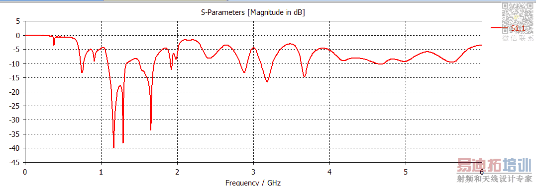
First without the frame
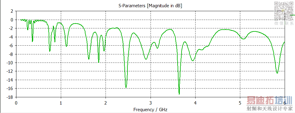
When the antenna is placed on the side of the frame with bolts
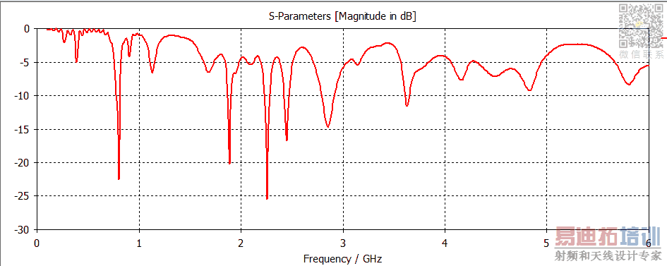
When it is placed at the bottom of the frame without bolts
I have used the material for the frame as Aluminium and (patch and ground plane of antenna as copper pure)
clearly ground plane of the CubeSat does affect your patch antenna. Initial resonance is at 1.2GHz, got shifted with the frame is attached.
I would like to see the orientation of the patch antenna on the CubeSat. I suspect antenna radiation pattern is affected by the frame.
you should compare the antenna efficiency of standalone antenna vs antenna with the frame. i guess you will see substantial efficiency reduction with the frame.
when i say ground plane of frame does not affect the antenna performance, i assume there is proper space between the antenna and the frame of the CubeSat.
How do we fix the Antenna to the frame ?
you have to retune the antenna with the frame attached. meaning you have to reoptimize the antenna with the frame attached. adjust the parameters of the patch antenna to get back the resonance frequency and the efficiency. efficiency for sure wont be as good as standalone antenna but if its meets your requirement, its good enough.
meaning how much space should be there between the antenna and the frame? what is used to fix it to the frame ?
usually designers will have size constraints. i believe you have your satellite size constraint. i wont be able to tell how much space you need because is an EM simulation problem. you can do parameter sweep in CST by varying the distance between frame and the antenna to understand the distance needed.
you can use any material to screw/fix the antenna to the frame but it shouldnt be touching the antenna. it will great if the screw/material is far from antenna. you can change the distance and observe the simulation to fix a location.
Here are the images when I placed the antenna below the frame and in front
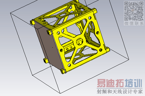
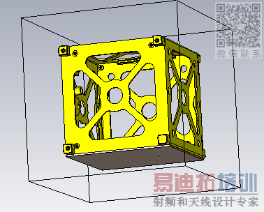
i think i know the cause of your problem. currently the ground plane of the patch is at the outer area and your patch itself is touching the frame. is it correct?
if yes, you have to flip your patch antenna. your patch antenna shouldnt be touching any part of the frame.

