How To Extract PCB RFID Antenna Circuit model Using CST
Dears;
how i can extract SPICE Model For This attached Antenna Using CST Tool i can feed the antenna and do Frequency Analysis and drow the Far Filed Pattern if there any post calculation to Extract Circuit model For this antenna or Calculate it's input impedance.
it is RFID Antenna work @ 13.56MHz
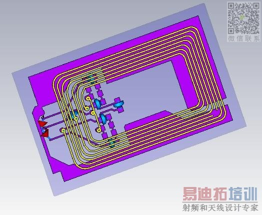
I'm not using CST for 13.56 MHz RFID coils analysis, some general comments nevertheless.
13.56 RFID is essentially a near field problem. The radiation impedance part of the coil's real impedance can be usually neglected, the far field is mainly interesting as an unwanted EMI.
The coil or "antenna" impedance can be derived by an AC magnetics analysis, without considering EM phenomena (coupling of a electrical and magnetical field).
The real part impedance is mainly representing coil resistance, skin effect and eddy currents.
CST calculates the input return loss (S11) . This contains the input impedance information. I am not a CST user, but other EM simulators aloow you to plot the real / imag part of the input impedance (Zin) also. This data/plot should be available in CST as well.
Of course, S11 contains all necessary information. As said, the real part will mainly represent conductor losses. So you should take care, that the simulation parameters will allow a sufficient accuracy of current distribution modelling.
Hi, actually i have seen ur antenna! can u plz send me details of antenna that u have designed? means any pdf or doc file that contains the description?
Dear i attached the antena matching circuit and its PCB coil
i will try to upload sct file later
f
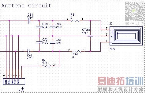
- - - Updated - - -
you can download CST file from this link
http://www.4shared.com/file/fNszCwUq/RFID_R_2.html?
The rigid-flex pcb prototypes is the most famous and popular electronics product which we needed for the making pcb. We used lot of electronic product at home and office were the rigid-flex pcb are used.

