Problem calculating charasteristic impedance of port on CST
Hello, i am new here in the forum. I have one question on CST Microwave Studio. . So i have a restrangular waveguide with e=5 μ=1. I use a waveguide port to put energy. I want to estimate the charasterist impedance Zo. I think that this must be 50 Ohm for most of RF circuts. So i have |s11|=0,62 and magnitude Zmatrix(1,1)=300. So we have s11=Zload-Zo/Zload+Z0=>
Zo=70 Ohms. So i am wrong. Then i went to transient solver and i put normalize to fixed impedance 50 and adaptive mesh refinement. I run again and s11=0,97 Zmatrix(1,1)=257 so, Zo=3,91 ! I thougt that now it should be 50 Ohms. I don't know what is wrong. I have 30 lines per wavel and 30 lower mesh limit at mesh properties.
Friendly George
Ι read in other posts that parameter s11 is complex number and of course Zmatrix is too. So i took the formula,
s11=Zload-Zo/Zload+Z0 for s11,Zload complex numbers i did the division and Zo is not again 50ohm. Is anyone tell me if the characteristic impedance of port is always 50 ohm or it changes. If it changes why ? Is any option in CST that i can fix on the Zo?
Thanks a lot
Thirst of all, for a wageguide we don't say "characteristic impedance" but impedance of the mode TEmn or TMmn. Thus, the mode is important because impedance varies versus it. So my first question : at what frequency do you simulate your waveguide ? second question : have you authorized one or several modes ?
If you work with the fondamental mode , say TE10 , so the formula to calculate the impedance of that mode is very simple and you don't need a simulation. If you work with another mode the formula is simple too.
Ηi, i don't want to calculate the impedance of the modes.These are shown from Cst . I want the characteristic impedance of the transmission line Zo, that feed the waveguide that i have design. Check the image.Specifically, i take the vector s11 and Zmatrix(=Zload) vector, the formula s11=Zload-Zo/Zload+Z0 and calculate Zo. I think that this must be 50 ohm. I use fresonance=7.5 Ghz and i watch only TE10 mode with fcut=6.5 Ghz. With all these we are ok ? If it is ok the anwer is that, characteristic impedance of port is always 50 ohm or it changes. If it changes why ? Is any option in CST that i can fix on the Zo?
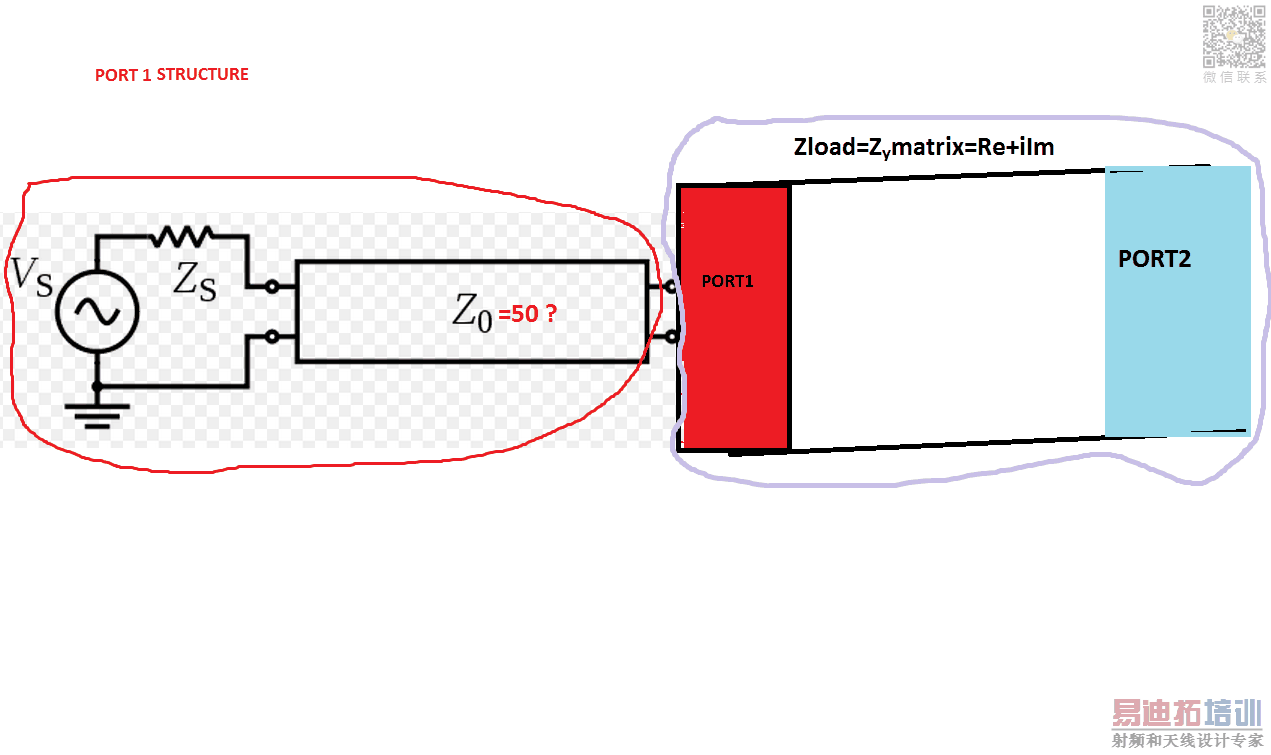
For me, it is not very clear.
If i have undersood, you want to determine the characteristic impedance of a line loaded by a waveguide in TE10 mode at 7,5 GHz.
I don't know CST but only HFSS,ADS and Ansoft Designer. But why do you suppose that Zo is equal to 50 ohms. Of course it is almost the case but it depend of the geometry of your line (Microstrip, coaxial, stripline or another one...).
Could you send a copy screen of your schematic realised in CST ?
Normally, impedance of normalisation is chosen in the software in order to represent impedance in the Smith shart.
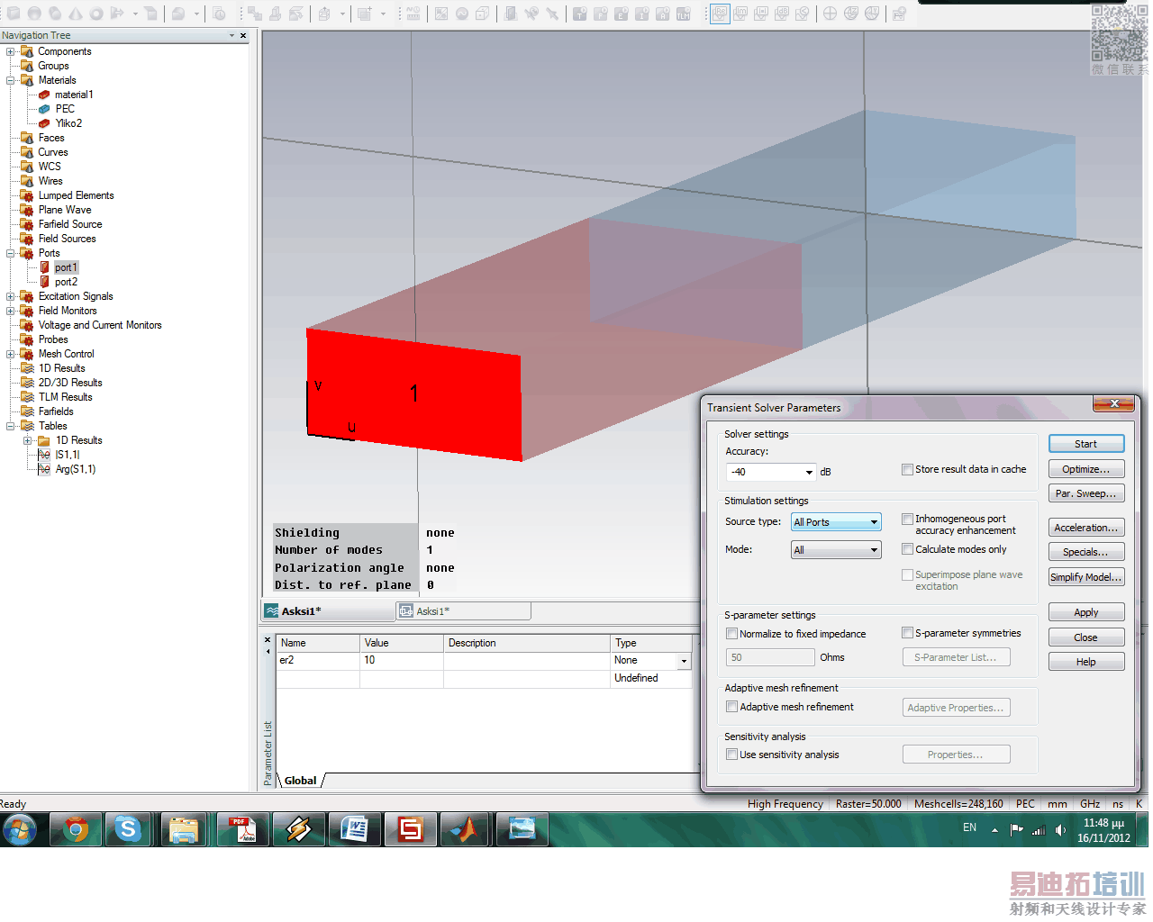
I suppose that Zo is equal to 50 ohm because that's i know that cst do. But why the Zo should change if i change the dielectric parameters of the wageguide ? The Zo depend on geometry of the port(it is constant i don;t change) and from (R,C,er of port) but i don't change them. So the Zo should not change....
Well,
I have no new idea, in hfss, the wave port is matched to the mode exiting the wave guide.so, the s11parameter is always null. As soon as i have a new reflexion, i will post it.
ok my friend i appreciate your try ! Also you must consider that i want to proof that Zo=50 or what, and with formulas like the above that i have write, so i want and a mathematical solution.
Thanks for all
George
As I wrote in your other thread, the waveguide port Z0 is not fixed ("generalized S-parameters"). It depends on the waveguide dimensions. If you fill the waveguide with dielectric, that will also change the impedance.
See "Wave impedance in a waveguide" http://en.wikipedia.org/wiki/Wave_impedance
Hi,
The "characteristic impedance Z0" you are referring to is not 50ohms in a waveguide. In fact there are various ways to define it (e.g., current-voltage, power-current, power-voltage, etc). This is because in a waveguide operating in the TE/TM mode the voltage is not defined unambiguously (it depends on the integration path) in contrast with a TEM transmission line where everything is uniquely defined. Now, in CST the S-parameters are normalized by default to a value that minimizes the reflections. This value changes with frequency because the wave impedance changes with frequency. Thus, these S-Parameters are normalized to a frequency dependent impedance in order to obtain minimum reflections over the whole frequency range (similar to HFSS). In your case this impedance is the wave impedance of the fundamental mode. By normalizing the S-Parameters to 50 ohms ( a value that is chosen arbitrarily and does not correspond to any physical quantity in your deign) you effectively eliminate the frequency dependency and normalize the S-Parameters to a value that does not minimize reflections (it's not matched to the port). Once you've done this, you are not allowed to use the formula you mention above since Z0 is now known a priori (50 ohms) so you cannot solve for it.
As other people said previously, it's the wave impedance you are interested in (as the terminology characteristic impedance is usually used for TEM transmission lines).
If I got it right, you are interested in feeding a waveguide and therefore you want the impedance of the feed line matching that of the waveguide. My suggestion would be to try to simulate the whole device (feed line and waveguide) and optimize this instead. The reason is that if you are using a coax cable to excite a waveguide (i.e., a probe or a loop), is quite difficult predict the impedance of the probe/loop itself. What you will have effectively is a coax cable (with known characteristic impedance - 50 or 75 ohms usually - and and antenna formed by the stripped off part of the cable. Therefore, you need to adjust the geometric parameters of the probe/loop (assuming the the coax/waveguide have fixed dimensions) in order to obtain good coupling and hence, good impedance matching.
Hope this helps!
Hi stergios thanks for you reply! DO you have any relation with Greece?cause your name is common here So i want to be sure if the Zo of the feed port is always 50 Ohm or not ? I now that when we make an antenna for example the feed ports have specifics resistance (50,75,100) so i want to be sure if my structure is realestic. Ι am a little puzzled ...
So you say to me that if i activate the "normalize to 50 ohms" is not good if i want to represent my structurre for real (?) You can take a look to some images that i have uploaded before.I don't have feed line in my structure, i have a waveguide port only. I thought that Zo of the waveguide port depend on geometry of the port(it is constant i don;t change) and from (R,C,er of port) but i don't change them. So the Zo should not change.... ! So the Zo shouldn't change if i activate 50 ohm option or if i don't activate it? This i don't understand. I think tha s parameters change when Zin(of waveguide) change (for example if i change the material but i though that the Zo of the port is constant. With activate 50 i have s11 magnitude 0.96 and without it 0.40. Which is real? Damn
From the other post : Icase) Without normalize to 50Ohm, for e=2 and some specific dimensions, a waveguide port gives |s11|=0,40 phase=93degrees and |Zin|=|0.29+i2591|=2591Ohm with phase=89 ,also VSWR=2,31.
IIcase) With normalize to 50Ohm the same one is: |s11|=0,94 with phase=14degrees, and |Zin|=|0.39+i2591|=2591 ohm and phase=89, also VSWR=36,13 .
I am so newbie and i am sorry for not understand some thinks.Thanks a lot for all
- - - Updated - - -
Hey bro thanks for your answers. I understand that if i change the Zin (of the waveguide) change S11 and Zo. But in real structure the ports have constant resistance Zo. So, the question is To activate or NOT the option of CST "normalize to 50 ohm".
The 50 ohm line impedance is a concept from TEM lines. For waveguides, it makes no sense to normalize to 50 Ohm.
Yes, I'm Greek as well....The port impedance is not 50 ohms in the software. For example when designing an antenna one makes sure that the feed line has a characteristic impedance that matches that of the transmission line that is going to be connected to. In most cases the excitation is a coax probe with Z0=50 ohms thus the antenna feed line (e.g., microstrip line for some printed antennas) is designed to have a characteristic impedance of 50 ohms (by selecting appropriate geometric/material parameters). In this case, practically you will see no difference if you normalize your port to 50 ohms or not. This is because the port is already normalized to a value that minimizes reflections, and here this value is 50 ohms.
On the other hand, a waveguide does not have a "characteristic impedance" of 50 ohms. It has a wave impedance that is not 50 ohms. For example if you pick up a frequency point, say 7.5 GHz, and you are interested in the fundamental mode, you will see that the S-Parameters at this frequency point will not change if you normalize them with ZTE10@7,5 GHz.
I thought you wanted to connect sth to your waveguide. If not, my bad. Then it is quite straightforward. Just forget the 50 ohms ....:)

