Radiation efficiencies from CST MWS and ADS Momentum are too different
Hi friends,
I am comparing radiation efficiency of a printed dipole RFID tag on PET substrate with conductive ink as the conductor. I set the PET substrate as normal with dielectric constant 3.5, and conductive ink as normal with conductivity 1.6e6.
I got 97% of radiation efficiency from CST MWS 2010 but 82% of radiation efficiency from ADS Momentum.
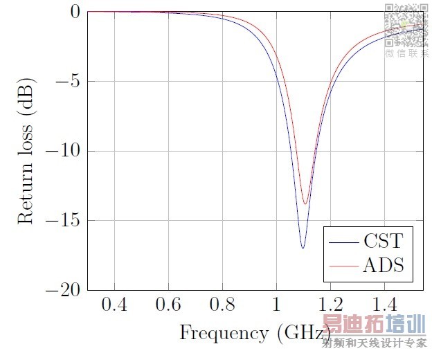
This result seems too weird. I have tried many ways in CST, such as increasing the mesh, changing the material to lossy metal or surface impedance in CST 2013, but the radiation efficiencies from CST and ADS are still too different. The s11 and impedance from both software agree well, but not with the radiation efficiency. Which radiation efficiency is more accurate and why they are different? Or... is there any recommended simulation settings?. If anyone who had ever compared radiation efficiency from these simulators, please share your opinion. I also attach my models. Thank you.
Does "radiation efficiency" in CST and ADS describe the same value?
Sometimes the impedance match is included in efficiency or gain.
Can you use something like "realized efficiency" or "realized gain" in CST? This should include the matching.
Have you compared the directivity?
Hi flanello, thanks for your reply.
Yes, the radiation efficiency in CST and ADS describe the same thing. In CST, I take the radiation efficiency from farfield monitor which describes [maximum gain(ieee)/directivity]. In ADS, I take it by calculating maximum gain/directivity shown in antenna radiation parameters. I am sure that the impedance mismatch is not included in radiation efficiency since there is also a parameter called "total efficiency" in CST which includes impedance mismatch.
I have also compared the directivity. The directivity from CST and ADS are not so much different, but the big gap comes from the gain. And I have no clue why the gain is so different.
Below is a screenshot showing gain, directivity, and radiation efficiency from CST and ADS for the model I attached in my post above.

Perhaps ADS includes the impedance mismatch in the gain? (The radiation efficiency and thus also the gain are lower in ADS, thus this could be an idea)
Have you compared the total efficiency from CST with the efficiency from ADS? Or what impedance do you have?
I
I am quite sure that ADS does not include the impedance mismatch in the gain. The total efficiency (include mismatch) is just about 30%. The total efficiency is very low because I take the efficiency in mismatch region (922.5 MHz). If ADS included mismatch in its gain, the gain/directivity should be lower than just 82% since the return losses are similar with CST.

I checked the current distribution from ADS and it is more distributed on the front surface and near the port, the maximum current density is about 2 A/m. In CST, the current is more evenly distributed on the dipole arm with the maximum current density 61 A/m. I am not sure whether the antenna gain and radiation efficiency are related to this issue or not.
hi, i have a question : how i can see radiation efficiency in cst ? in the farfield monitoring 3d view it cst shows gain and total radiation efficiency and radiation efficiency . is it correct? i need to do some calculation inorder to find the radiation efficiency of the antenna or that is what i am looking for?
Yes, it is correct. If you are using CST, you can easily find radiation efficiency in the farfield monitor which you set before simulation. Since radiation efficiency= gain/directivity, you can calculate it from gain and directivity appeared in farfield monitor as well.
i see -16 db in the farfield simulation ! but gain/directivity is -2db what is wrong? i can trust in which one?
my gain is higher than directivity!
but my gain dimansion is db and the dimansion of directivity is dbi how i can change dbi to db?
I have no idea and suggestion without seeing any screenshot or cst model
do u know em/circuite co simulation of cst? i use this feature
I know it, but I suggest you to make a new thread with detail explanation about your problem. It's quite difficult to understand if you give information piece by piece. So I think you'll get better solution and insight by opening your own thread
sorry ,i have posted a thread about em/circuite co simulation many time but no one answer it , i think nobody knows this feature of cst . :) i want toload a ring resonator with discrete elements my question is about :how define discrete port as illustrate in the attached picture whene i define discrete port in this two different way result is different which one is correct?
attached pictures


